Posted on July 4, 2018
What is wrong with me?
The last time I put a smart-ass sticker on the back of my car, it resulted in a ticket. Maybe this one will be okay. My vinyl cutter has cost me a lot more than I first calculated.

Posted on July 1, 2018
Time-Lapse 3D Print on Da Vinci miniMaker with 3rd-Party Filament
Thought I would share a time-lapse video I made using my SunPak 4K action camera ($28 knock-off of a GoPro). I printed a cool honeycomb pen holder (STL file found here on Thingiverse).

Posted on June 29, 2018
3rd-Party Filament on Da Vinci miniMaker Printer
So I picked up a barely used Da Vinci miniMaker 3D printer on eBay. It was very cheap ($24) because it was listed as “not working”. The description said it was missing the power supply. When it arrived I found that it looked to be in great condition. I dug through my bin of extra wall-warts and found a suitable power supply (24v DC 3.2A). I also found a suitable barrel connector and soldered it on. Once I plugged it in and powered it on all was well! It came with a nearly complete spool of filament that I burned through rather quickly. Because the Da Vinci printers use RFID to force you to use only their filament (4-times the price of normal PLA), I looked into my options.
I ended up picking up some nfc213 sticker RFID tags on eBay for less than 50¢ each and used the ReelTool android app (found here) to program/reset tags.
All that was left was to make a spool holder to allow the filament to feed up into the printer smoothly.
With a little guidance, my son designed, laser-cut, and assembled a holder.


Posted on June 22, 2018
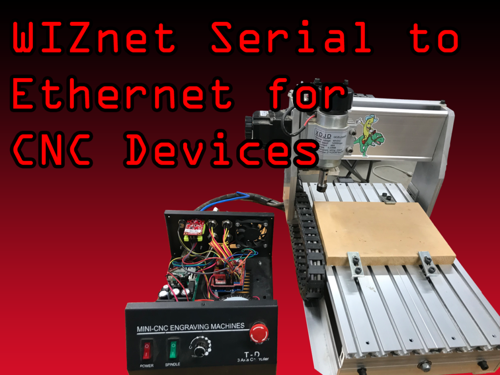
WIZnet WIZ750SR contest on Hackster.io submission
I finally completed my project for submission to the WIZnet Hackerster.io contest.
You can read all about the project here…
https://www.hackster.io/gmk/ethernet-connected-cnc-mill-or-other-machines-d0607a
Here is the content of my GRBL configuration file :
$0=10 (step pulse, usec)
$1=25 (step idle delay, msec)
$2=0 (step port invert mask:00000000)
$3=6 (dir port invert mask:00000110)
$4=0 (step enable invert, bool)
$5=0 (limit pins invert, bool)
$6=0 (probe pin invert, bool)
$10=3 (status report mask:00000011)
$11=0.010 (junction deviation, mm)
$12=0.002 (arc tolerance, mm)
$13=0 (report inches, bool)
$20=0 (soft limits, bool)
$21=0 (hard limits, bool)
$22=1 (homing cycle, bool)
$23=3 (homing dir invert mask:00000011)
$24=25.000 (homing feed, mm/min)
$25=500.000 (homing seek, mm/min)
$26=250 (homing debounce, msec)
$27=2.000 (homing pull-off, mm)
$100=400.000 (x, step/mm)
$101=400.000 (y, step/mm)
$102=400.000 (z, step/mm)
$110=500.000 (x max rate, mm/min)
$111=500.000 (y max rate, mm/min)
$112=250.000 (z max rate, mm/min)
$120=10.000 (x accel, mm/sec^2)
$121=10.000 (y accel, mm/sec^2)
$122=10.000 (z accel, mm/sec^2)
$130=196.000 (x max travel, mm)
$131=280.000 (y max travel, mm)
$132=100.000 (z max travel, mm)
Posted on June 10, 2018
Obligatory shop lighting upgrade
It only makes sense to upgrade the lighting in my shop to “enhance” my 3D printing and laser cutting endeavors.
Posted on June 8, 2018
3D Printer Auto-Calibration
So, I built my 3D printer several years ago when SainSmart offered to sponsor my build with their new line electronics. They sent me a RAMPS
1.4 board, Arduino Mega 2560, endstop switches, Smart LCD control panel, and four A4988 cards.


I opted to build the more rigid Ord Bot Hadron because I like the stability and the design. I found the mechanical frame on eBay for $25 from Switzerland and some NEMA 17 stepper motors from the US for $7 each.
I wanted to get fancy and make a dual-extruder printer. At the time, dual extrusion wasn’t quite as common. I designed an adapter plate that allowed me to mount the two extruders to the carriage and spent some time adjusting the Z position on both to keep them even. I had to tweak the Marlin firmware and do some calibration, but I got it to work.
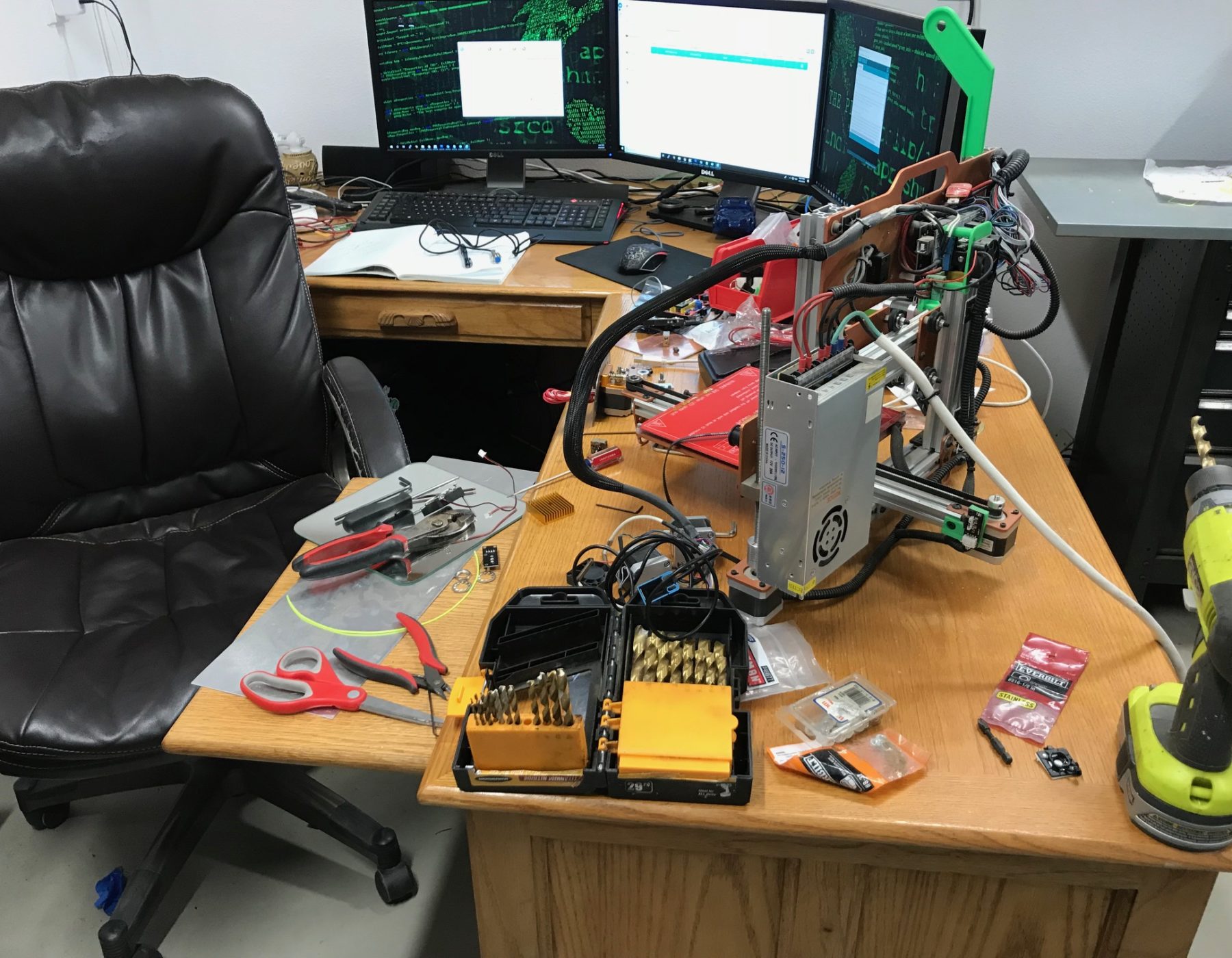
This was great, but I found that the build-plate adjustments were very crucial. Finally, four years later, I decided to put in an auto calibration function to eliminate the need for tweaking the level adjustment of the build plate. I’ve done a lot of research on sensors and considering the fact that I have a mirror as my build plate, I opted for a micro-switch attached to a servo. I also decided to remove one of the extruders to reduce the weight, which allows for faster print speeds.
I picked up a cheap MK8 extruder on eBay and installed it. I grabbed one of my cheap 9g servos that I had laying around and designed a switch mounting bracket that fit one of my spare micro-switches and the servo horn. I had to be careful to keep it slim enough to mount near the extruder without hitting anything. I have posted the .dxf file here for anyone that has access to a laser cutter and want to make one of their own.

For testing, I mounted the servo to the underside of the carriage and played with the position values to figure out the correct value for the switch to be stowed and the correct value for the switch to be deployed for sensing. I found this video to be VERY helpful…
I then mounted the servo using a metal 9g servo mounting bracket I had left over from my GPS AdventureBox Kickstarter project and dialed in the correct Z probe offset. The first layer of my prints are fantastic now!
Posted on May 13, 2018
Hack The Box
After completing the Offensive Security Certified Professional (OSCP) certification, I found myself lost. It is difficult to keep my skills on point while maintaining my “whitehat” status without a lot of overhead work in maintining a target network. A friend of mine directed me to a very active site that hosts many OSCP-like target machines and CTF-like challenges… https://hackthebox.eu
New machines are added regularly and access is free. You can pay for a VIP membership, which helps fund the site and gives you access to a much less crowded VPN environment.
Hack your way into an account here… https://hackthebox.eu/invite
Posted on May 4, 2018
Wiznet Hackster.io Contest
Thanks Wiznet and Hackster.io for selecting my project proposal and sending me a free dev-kit! Now time for integration!

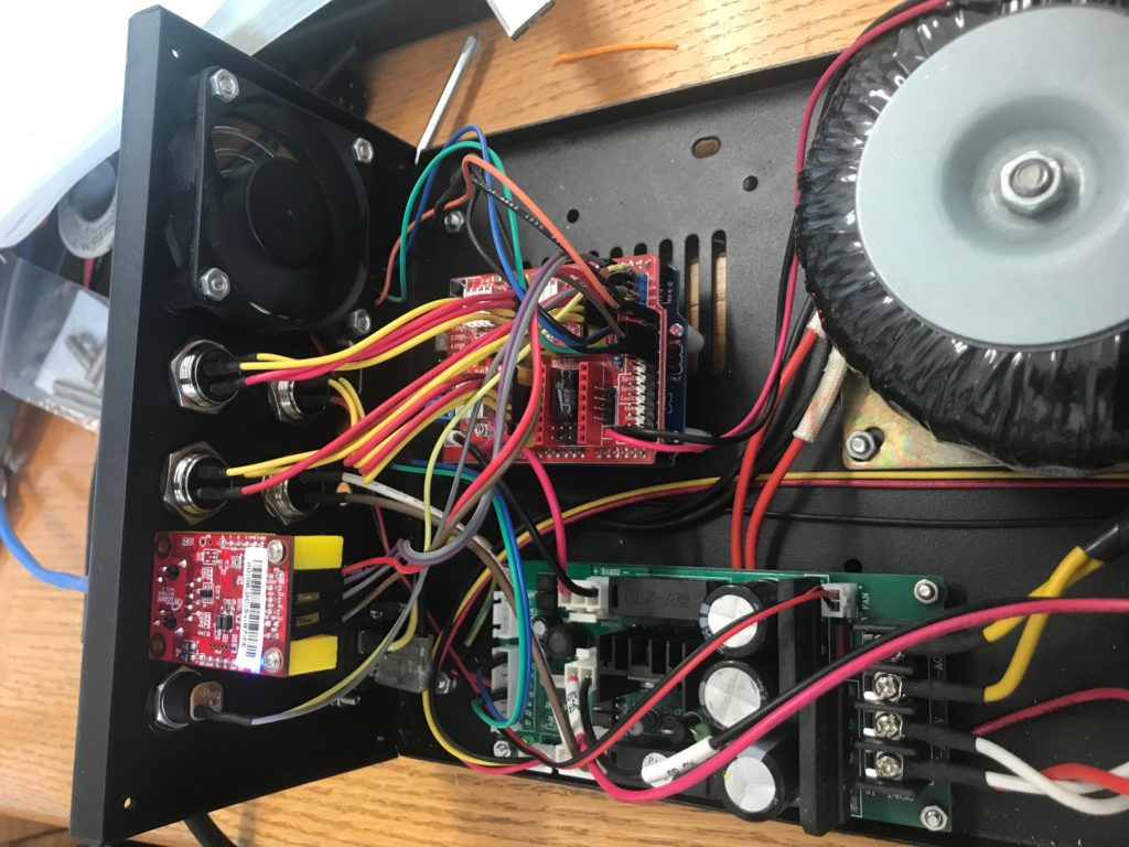
My proposal consists of integrating the WIZ750SR-EVB module with the CNC Shield to network-connect CNC devices. This could be very beneficial to maker spaces or other machine shops.

Posted on August 12, 2015
DEFCON 23 Robot Competition 1st Place!
I won first place this year! Big thank you to the contest volunteers, sponsors, and competitors!

Posted on August 14, 2014
DEFCON 22 Robot Competition 3rd Place